110 Results
View results:
Sort by:

RWIND 2 and RFEM 6 can now be used to calculate wind loads from experimentally measured wind pressures on surfaces. Basically, two interpolation methods are available to distribute pressures measured in isolated points across the surfaces. The desired pressure distribution can be achieved using the appropriate method and parameter settings.

When calculating regular structures, data input is often not complicated but time-consuming. Input automation can save valuable time. The task described in the present article is to consider the stories of a house as single construction stages. Data is entered using a C# program so that the user does not have to enter the elements of the individual floors manually.

The modal relevance factor is a result of the linear stability analysis and qualitatively describes the degree of participation of individual members in a specific mode shape.

The Construction Stages Analysis (CSA) add-on allows for the design of member, surface, and solid structures in RFEM 6 considering the specific construction stages associated with the construction process. This is important since buildings are not constructed all at once, but by gradually combining individual structural parts. The single steps in which structural elements, as well as loads, are added to the building are called construction stages, whereas the process itself is called a construction process.
Thus, the final state of the structure is available upon completion of the construction process; that is, all the construction stages. For some structures, the influence of the construction process (that is, all the individual construction stages) might be significant and it should be considered so that errors in the calculation are avoided. A general overview of the CSA add-on is given in the Knowledge Base article titled “Consideration of Construction Stages in RFEM 6”.

You can use the selection options in the printout report to receive the detail results (in short or long form) to illustrate the individual buckling modes with the relevant buckling analysis.

When modeling and designing glass panes in RF-GLASS, you have two different options for the FE mesh settings.

In RFEM and RSTAB, there are various options to renumber the individual structural elements, such as nodes, lines, members, surfaces, or solids. Two options are available for renumbering: singly and automatically.
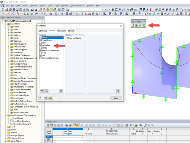
The tools arrangement in the workplace can make your work fast and efficient.

If you want to consider guide objects in the overall view (F8 key or double-click on the mouse wheel) or, for example, in a particular direction of the views, you can enable this option in the settings of the particular guide objects (guidelines, background layers, line grids).

A member's boundary conditions decisively influence the elastic critical moment for lateral-torsional buckling Mcr. The program uses a planar model with four degrees of freedom for its determination. The corresponding coefficients kz and kw can be defined individually for standard-compliant cross-sections. This allows you to describe the degrees of freedom available at both member ends due to the support conditions.
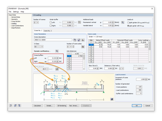
In the event of converting or extending a hall, the building owner may want to add a second or third crane to an existing crane runway. Since the original design usually does not consider other cranes, a common solution is to design a minimum distance between the cranes. This is done via the crane technology settings.
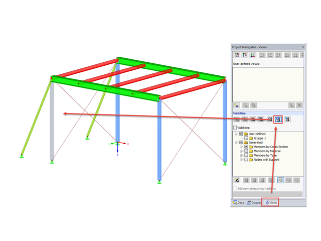
In RFEM and RSTAB, you can apply various visibilities in the Views project navigator.

In RF‑TENDON and RF‑TENDON Design, you can review and adjust the code‑dependent factors, calculation parameters, and calculation methods using the "Code" button. You can display the settings and adjustment options according to a chapter of a code, selecting the "Grouping" option in the dialog box.

The individually defined printout reports in an RFEM or RSTAB model can be displayed in different ways.

You can make various settings in order to achieve a clearly‑arranged display of the result values. For example, some users may not want the white background in text bubbles. You can adjust the background in "Display Properties" using the Transparent and Background color option.

Designing vertical insulating glass requires assigning different loads on the individual layers of the entire glass unit. This occurs, for example, with simultaneous actions from wind loads and fall protection.

In RFEM and RSTAB, you can visually check or display the materials used for members in the wireframe and solid models.

The RF‑/STEEL EC3 add-on module can perform the design of fillet welds for all parametric, welded cross-sections of the cross-section library. For this, the option must be activated in the detail settings of the module. As an alternative, you can also use a surface model for the design.

The additional loads from self‑weight are usually composed of several layers; for example, classic floor and ceiling layers in buildings, or road coatings for bridge constructions. When defining load definitions in RFEM and RSTAB, you can use the multi-layer load to define the individual layers with thickness and specific weight.
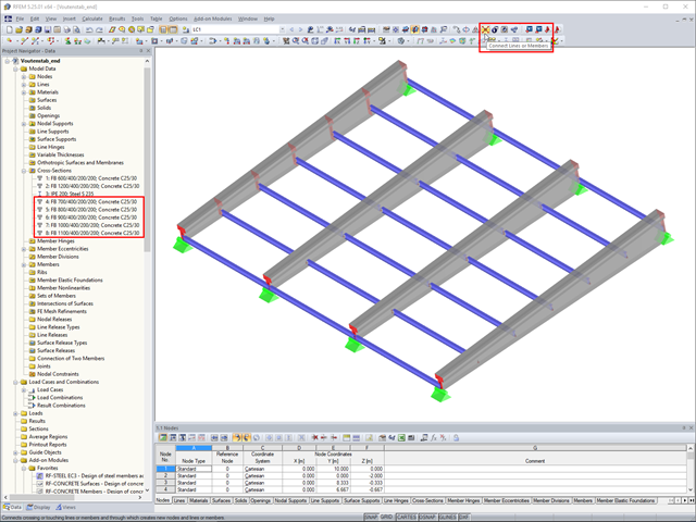
In RFEM, if you want to insert a tapered member with intermediate nodes into an existing model, the issue often arises how to determine the individual cross-section depths of the tapered members quickly. The "Connect Lines or Members" command comes in handy for this purpose.
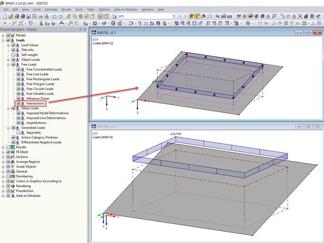
For free loads, RFEM allows you to display the intersections at the respective surface.

Once you have determined the final tendon geometry in RF‑TENDON, exporting the model to a CAD program can be useful. For this purpose, the module includes the option to export the file in the .dxf file format. You can select the export function by right-clicking the workspace. After selecting the DXF format and the storage location, additional settings can be made.

RFEM and RSTAB offer many display options in the Display Navigator. They can be completely different, depending on their function. You often have to click several times to make certain changes. If you want to optimize your work, you can create user‑defined views. In these views, you can save all specified settings. The following example illustrates this principle.
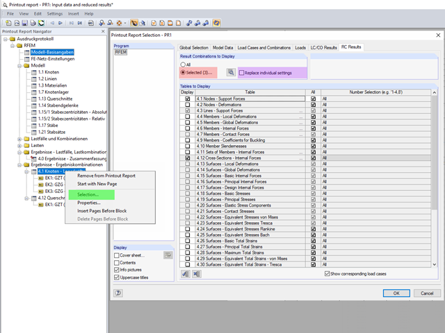
The content to be displayed in the loading and result tables can be managed in the global selection of the printout report (red).

In RFEM and RSTAB, different graphical representations of the foundation dimensions are available.

You can color the surfaces in the direction of the local z‑axis using the indicated option in the Display Navigator. By default, the side lying in the negative z-direction is colored red and the side lying in the positive z-direction is colored blue.
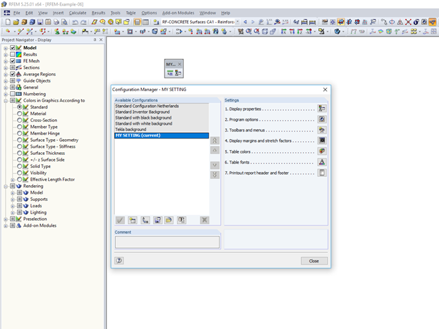
An individual user‑defined workspace can increase your productivity and make your daily work easier. This is why many users take the opportunity to adjust the toolbars in RFEM and RSTAB and to create their own toolbars containing the most frequently used commands.
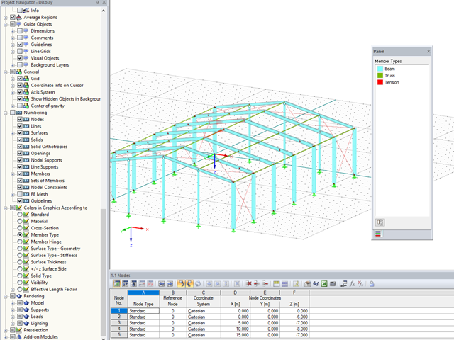
In RFEM and RSTAB, you can now also display and check the types of members used visually, by means of colors. To do this, an option has been integrated into the Display Navigator.
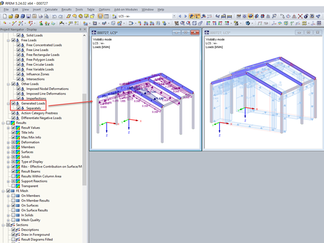
If, after defining the generated loads belonging together, you switch to the visibility mode, the loads are also shown on the hidden structural elements.

In order to detect the governing internal forces of a plate, a checkerboard loading is commonly used. Since it is not necessary to divide the surface into individual load segments, loading is usually carried out by means of free rectangular loads. In the case of many loads, the normal load display can become somewhat confusing.